A bootloader is the first program that runs when a device starts. Its job is to prepare just enough of the hardware to load an operating system kernel or application into memory, then hand over control. That small handoff decides whether a PC reaches its desktop, an Android phone verifies its software, or a field device can recover from a failed firmware update.
How a Bootloader Works From Power-On to Kernel
At power-on, RAM is empty; only code in non-volatile storage is available. The CPU therefore starts at a predefined reset address, usually in fixed boot ROM. This factory code initializes only what is needed first: the CPU, memory controller, and basic I/O. It then looks for the next boot stage on a storage device.
- Start from immutable code. The processor runs boot ROM after reset; an x86 PC instead runs BIOS or UEFI firmware from a flash chip on the motherboard.
- Initialize enough hardware to continue. Early code makes memory and a boot device usable before it searches for a larger program.
- Load the next boot stage. A small first stage may load a more capable second-stage bootloader from storage.
- Load the kernel and transfer control. The second stage places the kernel in RAM, supplies items such as a device tree, command-line arguments, or an initrd location, and jumps to it.
The name comes from “bootstrap loader”: a small first program loads the next, larger one. The idea dates to the early 1950s.
Two PC Startup Paths Lead to the Same Handoff
| Path | What firmware loads | Key constraint or capability |
|---|---|---|
| Legacy BIOS | The first 512-byte sector of the boot device: the Master Boot Record (MBR) | The MBR holds first-stage code and the partition table; its last two bytes must be 0x55 and 0xAA, the boot signature. |
| UEFI | An EFI application from the FAT32 EFI System Partition (ESP) | UEFI uses GPT, supports 32- or 64-bit operation, and can enforce Secure Boot. |
After its Power-On Self Test, legacy BIOS reads the MBR, places its code at address 0x7C00, and jumps to it. BIOS runs this code in 16-bit real mode and is limited to MBR disks of up to 2 TB.
UEFI reads the GUID Partition Table, finds the ESP, and loads an EFI application directly, typically \EFI\BOOT\BOOTX64.EFI on x86-64. GPT disks can be up to 9.4 ZB.
Why Larger Bootloaders Need a Second Stage
A first stage is kept small on purpose. A second-stage bootloader such as GRUB or full U-Boot can understand file systems, select a kernel from a specific partition, and present a menu. When that menu offers multiple boot choices, the program is often called a boot manager.
For Linux, GRUB can load a bzImage, a Multiboot-compliant kernel, or chain-load another boot loader such as Windows Boot Manager. On board-level hardware, full U-Boot follows a different path: the on-chip ROM loads a stripped-down Secondary Program Loader (SPL). The SPL initializes DRAM, often using CPU cache as RAM, and then loads full U-Boot.
This staging is useful because early code cannot assume that ordinary memory or storage services already work.
Where the Bootloader Lives Depends on the Device
On a legacy BIOS PC, boot code can live in the first 512 bytes of the disk’s MBR or in the boot sector of an active partition. On a UEFI machine, boot loaders are .efi files on the FAT32 ESP.
Microcontrollers follow the same idea on a smaller scale. Many STM32 parts contain a built-in ROM bootloader in system memory; at reset, the BOOT0 pin selects main flash (BOOT0 = 0) or the ROM bootloader (BOOT0 = 1). A custom in-application-programming (IAP) bootloader can instead occupy the first section of flash memory. Depending on the platform, U-Boot may load from an SD card, SATA drive, NOR flash, or NAND flash.
Firmware Updates Work Because the Update Logic Starts First
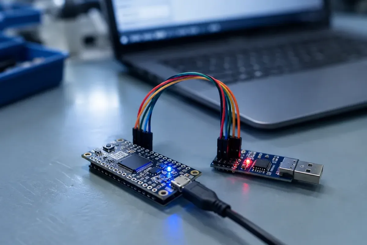
In embedded systems, a bootloader enables firmware updates without a JTAG or SWD hardware programmer. By separating the update path from application code that changes regularly, the device retains a recovery path when an application update fails.
A custom MCU bootloader can, for example, receive new firmware over UART, USB, Ethernet, or CAN, store it temporarily, erase the application region, and write the replacement image. In automotive devices, bootloaders commonly listen for CAN update frames, write the image to flash, and verify it before booting. With dual-bank flash, one bank can run while the other is programmed, followed by an atomic switchover.
Updating the bootloader itself is different: a failed self-update can brick a device unless a recovery mechanism such as a ROM bootloader remains available.
What a Minimal Bootloader Looks Like
On an ARM Cortex-M microcontroller, the smallest useful bootloader only has to run at reset and jump to the application. The application’s vector table begins with its initial stack pointer, followed by the address of its reset handler. The bootloader points the vector table offset register (SCB->VTOR) at that table, loads the stack pointer, and branches to the reset handler. The example assumes an STM32F4 with a 16 KB bootloader in the first flash sector:
#include <stdint.h>
#include "stm32f4xx.h"   /* CMSIS device header */

#define APP_ADDRESS 0x08004000u  /* application starts after 16 KB */

typedef void (*app_entry_t)(void);

void jump_to_app(void)
{
    uint32_t app_sp    = *(volatile uint32_t *)APP_ADDRESS;
    uint32_t app_reset = *(volatile uint32_t *)(APP_ADDRESS + 4u);

    __disable_irq();          /* the application re-enables interrupts */
    SCB->VTOR = APP_ADDRESS;  /* use the application's vector table */
    __set_MSP(app_sp);        /* load the application's stack pointer */
    ((app_entry_t)app_reset)();
}
A real bootloader adds the useful parts around this jump: it checks whether an update is pending, verifies the application image, and stops any peripherals it started before handing over.
Secure Boot Makes the Handoff a Chain of Trust
With secure boot, each component verifies the cryptographic signature of the next component before executing it. The root of trust sits in hardware, such as CPU fuses, a dedicated security chip, or boot ROM, so software cannot alter it. UEFI Secure Boot checks boot components against trusted certificates stored in the firmware.
Android applies this principle through a vendor-proprietary bootloader. It brings up the kernel, guards device state, and verifies the boot and recovery partitions. Since Android 8.0, Android Verified Boot extends a chain of trust from a hardware-protected root through verified system, vendor, and OEM partitions. It also checks version numbers to block rollback to an older vulnerable OS.
Android Unlocking Changes What the Device Will Trust
Most Android devices ship with a locked bootloader, so users cannot flash partitions until they unlock it. After unlocking, the device permits unofficial or unsigned OS images, custom recoveries, and root access, but it removes the guarantee of software integrity. With physical access, an attacker then has a chance to alter the boot sequence, extract data, or install persistent malware.
On devices that allow it, you first enable OEM unlocking in Developer options, then run two commands from a computer:
# restart the phone into fastboot mode
adb reboot bootloader

# request an unlock (erases all user data)
fastboot flashing unlock
After a reboot to bootloader, most Android devices enter fastboot mode, a USB protocol used to flash boot, system, and recovery partitions; it can also lock or unlock the device and query variables. The unlock command triggers a factory data reset, and relocking with fastboot flashing lock does too. On an unlocked device, some banking, wallet, and DRM streaming apps may refuse to run when integrity checks detect its state.
Common Bootloader Myths That Hide the Real Trade-Offs
- “A bootloader is the operating system.” It is a separate program that runs first and then passes control to the operating system’s kernel.
- “It is always one tiny program.” On a PC or board, fixed ROM code, a first stage, and a feature-rich second stage can all contribute.
- “Unlocking only adds customization.” Besides permitting unsigned images, it changes the device’s software-integrity and physical-access risk.
- “Firmware updates overwrite only the application.” Although a bootloader can update the application region, replacing the bootloader itself carries a separate bricking risk.
Frequently Asked Questions
What is a bootloader?
A bootloader is a small program that runs right after power-on, prepares the hardware, loads the operating system kernel or application, and hands control to it.
What is the purpose of a bootloader?
Its primary purpose is to prepare the execution environment, load the kernel and what it needs into RAM, and hand control to the kernel after power-on.
What is a bootloader on Android?
It is a vendor-proprietary image that brings up the kernel, guards device state, and verifies the boot and recovery partitions.
What happens if I unlock the bootloader?
The device can accept unofficial or unsigned OS images and custom recoveries, but unlocking factory-resets the device and removes a guarantee of software integrity.
What will happen if I reboot to bootloader?
On Android, the device enters fastboot mode, where a computer can communicate with the bootloader over USB to flash partitions, change lock state, or query variables.
Where is a bootloader stored?
On a BIOS PC it sits in the MBR or a partition boot sector, on a UEFI PC as an .efi file on the EFI System Partition, and on a microcontroller in ROM or the first section of flash.
What are the different types of bootloaders?
Examples include PC-oriented GRUB and Windows Boot Manager, UEFI boot managers such as systemd-boot and rEFInd, board-focused U-Boot and Barebox, and ROM or custom flash bootloaders on microcontrollers.